
GTP-U experiment and security consideratiion
User Plane protocol stack in 5G
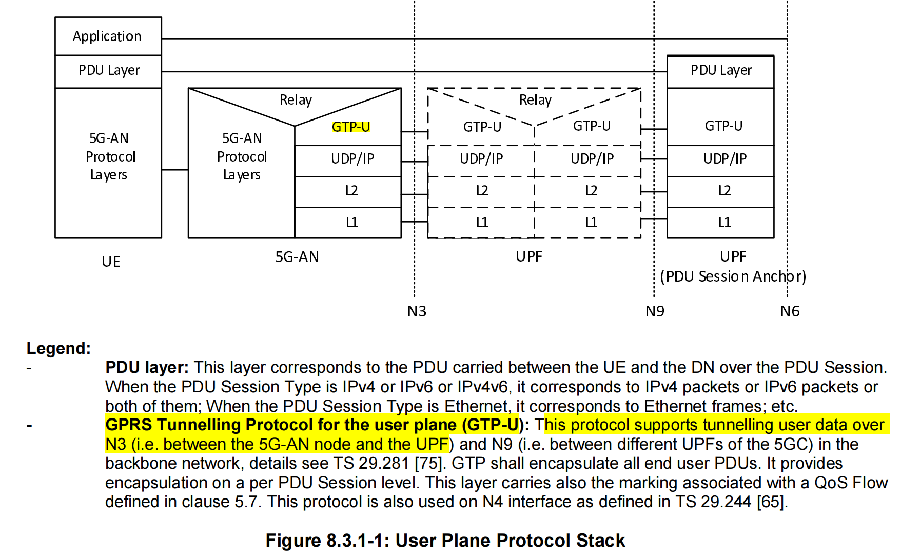
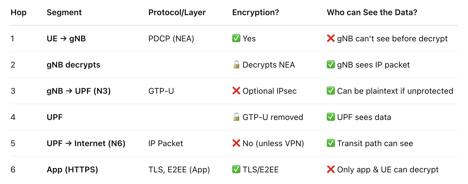
Transmission path of data
Experiment Setting:
After initiating the srsUE and srsgnb, the memory usage is as follows:
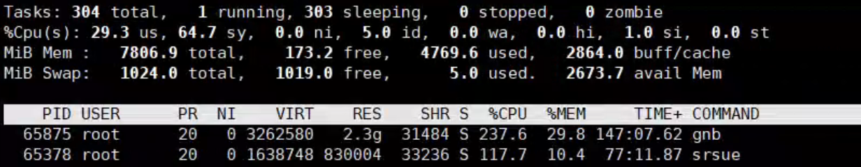
We install Open5GS and srsRAN both in the Raspberry pi 4 8G.
When we ping UPF address, and see what the GTP-U packet is like, we use
1 | sudo tcpdump -i lo udp port 2152 -n -vv -w gtpu_test.pcap |
Where the lo represents localhost since the Open5GS config uses loop back addresses for each function. Only the UPF has an public ip address who needs to communicate with the Data Network. Thus, in this network, we need to transfer the message to another NIC to be able to ping the public network. We adopt NAT.
First we open the IP forwarding,
1 | sudo sysctl -w net.ipv4.ip_forward=1 |
Then we configure the iptables:
1 | sudo iptables -t nat -A POSTROUTING -s 10.45.0.0/16 -o wlan0 -j MASQUERADE |
uses wlan0 to access the public. All the traffic will be forwarded to wlan0.
And also, Open5GS default will not automatically route UE to the gateway 10.45.0.1, we need to add this:
1 | sudo ip netns exec ue1 ip route add default via 10.45.0.1 dev tun_srsue |
Experiment and packet capturing:
Then we test
1 | sudo ip netns exec ue1 ping 8.8.8.8 |
It works now. And we use wireshark to capture packets.
1 | sudo ip netns exec ue1 tcpdump -i tun_srsue -w ue_traffic.pcap |
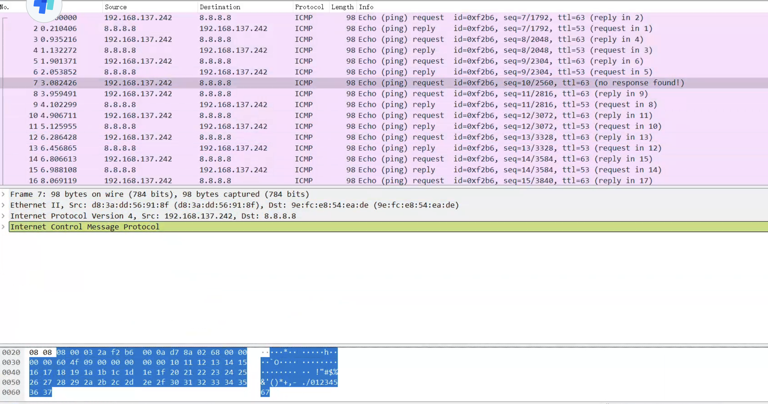
We capture all the traffic through tun_srsue, and save them into a pcap file.
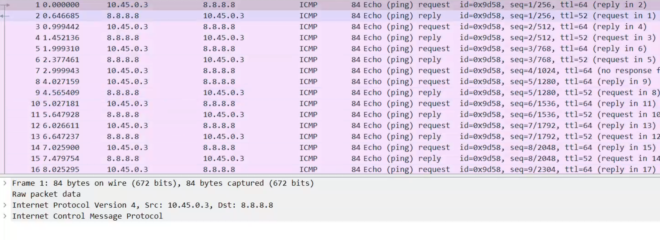
Note, this pcap file is captured on the tun_srsue interface in the UE, so it is sent by the gNB. Thus, we cannot see any GTP-U or NAT trace, only we can see is IP packet, the source IP is UE and the dest IP is Application Server.
Now we want to see the GTP-U first, so we should capture at the lo interface as above:
1 | sudo tcpdump -i lo udp port 2152 -n -vv -w gtpu_ping_8_8_8_8.pcap |
Then we can see the file content as follows:
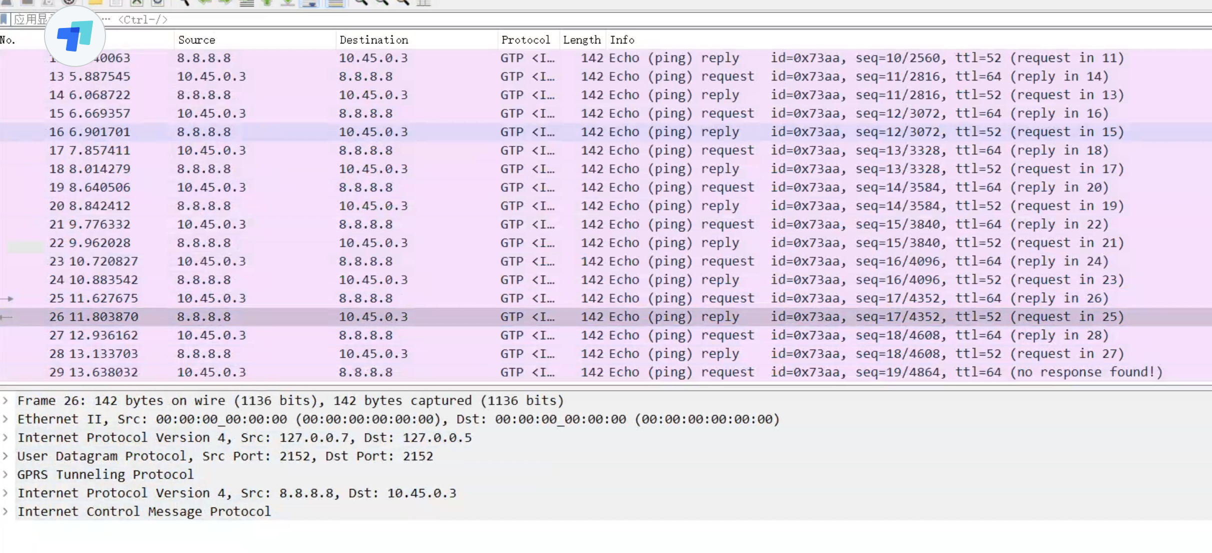
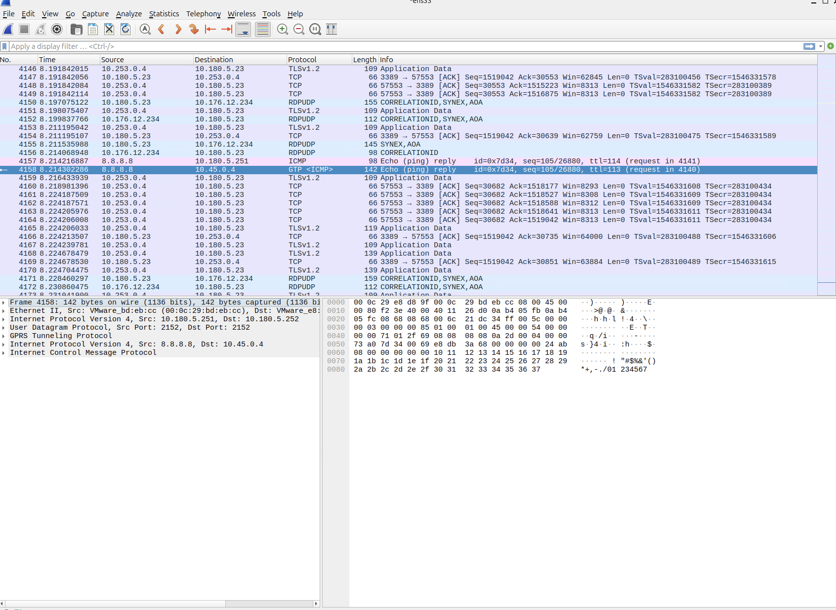
The packets using GTP-U protocol are sent between the gNB and the UPF, after they arrive at gNB, gNB will decap the GTP-U protocol and send the inner IP datagram to the UE.
When UPF receives GTP-U packets, it will decap GTP-U and send the PDU, namely inner IP protocol and upper layers, but change the source IP to the outbound IP of the UPF. This is the NAT technology, and the UPF’s outbound IP will replace all UE’s IP, to communication with the data network, replacing the UE.
Experimental result:
for UE: We use iperf to send messages to the UPF (through gNB).
1 | /srsRAN_4G/build/srsue/src# sudo ip netns exec ue1 iperf3 -c 10.45.0.1 -i 1 -t 60 |
For UPF:
1 | iperf3 -s -i 1 |
Second Experiment
下面放一张ping google.com的时候的截图,我们回顾一下GTP-U的报文结构
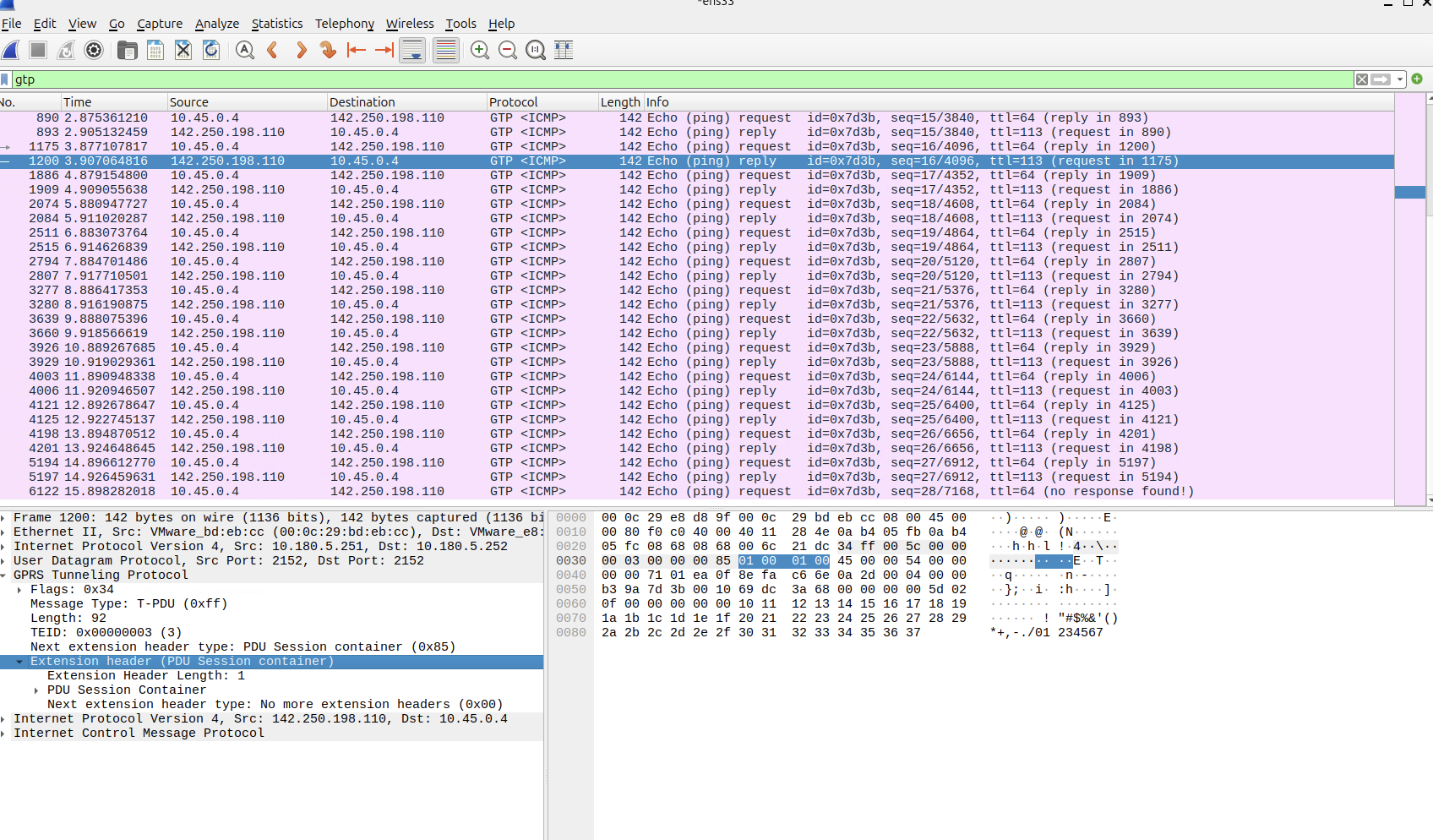
可以看到包括Flag, Messages, Length, TEID, Next extension header type,这里是数据,所以是PDU Session Container.
根据3GPP规范,Extension header的总长度是4个字节,所以看到GTP-U最下方就是这部分内容。
打开Flag我们可以看到
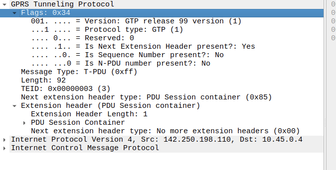
标识得很清楚,包括协议版本等。
 wechat